

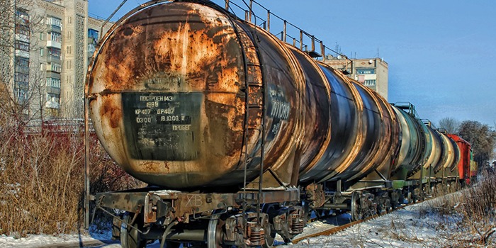
TIMM: Are your tank wagons at risk of electrostatics?
Larger amounts of liquids can be transported long distances in a more eco-friendly way in railway tank wagons as opposed to road tankers.
In oil & gas, this is typically between ports, refineries, storage depots, distribution depots and industrial consumers. Block trains are used to transport very large amounts of liquid, while individual tank wagons are used for smaller quantities.
Loading and unloading of the tank wagons takes place at terminals of all sizes. Applied loading technologies include mobile transloading systems, top loading platforms with hoses or drop pipes, on-spot loading facilities with one or more loading spots, or series-loading gantries with one or multiple tracks.
Unloading usually takes place from the bottom of the wagon through connected hoses or arms. In terms of automation, the terminal may range from manual operation up to being a facility with remote-controlled shunting and automatically positioned filling lances.
Top loading dome cones can house a high-level sensor to prevent against overfilling and a vapour return line. Quantity pre-set, flow control, metering/weighting and DCS visualisation are common at highly frequented terminals.
Railway top loading gantry
When handling tank wagons with crude oil, fuels, petrochemicals or chemicals at rail terminals, an explosive atmosphere is very likely. This is built by evaporation of flammable gases from the transported liquid as follows:
- Evaporation happens inside the tank
- When opening the dome hatch or loading couplers, the flammable vapours escape. Vapours are heavier than air and are spread on the ground through cavities. They mix with the air to form explosive mixtures
- Vapours can spread over great distances and be present even in remote places
- Liquid flashpoint determines evaporation
The specified flashpoint of the liquid provides an indication of the liquid surface temperature when evaporation starts. Uncertainties to this indication may result from the actual temperature inside the tank, air concentration or liquid mixture [IEC TS 60079-32-1:2013, Section 7.1.1]:
- In areas of high ambient temperature and strong sunlight, flammable atmospheres may even occur at liquids that have flash points above 60 °C.
- The concentration of the flammable vapours in air determines if a mixture is flammable or not. When handling a liquid at a temperature well above its flash point, the saturated vapours may result in a non-flammable atmosphere. But in practice, the actual atmosphere above the liquid may not be saturated (e.g. because of ventilation) and so may be flammable.
- Residues of volatile liquid or vapour from earlier operations with the same equipment or from nearby operations can contribute to a flammable atmosphere. Residual vapours may occur during switch loading, when a liquid having a high flash point (e.g. diesel) is loaded into a tank which previously contained a liquid with a low flash point (e.g. gasoline).
Last but not least, future liquid specifications should be taken into consideration. For instance in the field of bio fuels, mixtures may change the evaporation behaviour.
If it cannot be ruled out with certainty that a flammable atmosphere may be present, rail tank wagon loading or unloading facilities should be classified as hazardous areas. This avoids potential risk from existing ignition sources, including such as electrical equipment being installed and used.
Electrostatic charge accumulation and dissipation
Electrostatic charges result in a source of energy capable of igniting an explosive atmosphere. Liquids can become electrostatically charged when they move through pipes and hoses. Mixing, spraying or splashing can also create highly charged liquids or mists. The generated charges can accumulate either at the liquid or on isolated equipment and surfaces. An uncontrolled discharge of static electricity can provide enough energy to ignite the mixture.
To avoid sparks, a dissipative connection must be established between every piece of plant equipment and the tank wagon itself to the earth. Arising charges by loading or unloading processes can then be safely diverted to earth potential.
Electrostatics are a physical phenomenon characterised by very high electrical voltages, (up to 20,000 V), and very low electrical grounding currents at the same time. A resistance of 1 MOhm is considered sufficient by international standards to safely dissipate the electrostatic charges.
In contrast, there are publications which discuss considerably lower dissipation resistances, (such as 10 Ohm). But these values do not result from the physics of discharging electrostatics. Rather, they are an expression of the practicability to verify the presence of the grounding connection.
The reason is very simple: Low resistance values can be measured by using simple measuring equipment. Existing damages or interruptions of the grounding connection can be identified easily, by using a multimeter, for example.
Checking resistance before every loading operation
This is where ground indication monitors come into play. Grounding control devices are set up to verify a grounding connection and avoid the accumulation of electrostatic charges at the railway wagon. They reduce the time required for manual checks of grounding lines and dissipation paths.
When using grounding control devices capable of impedance measuring, the limit value of 10 Ohm should not be applied, because it unnecessarily affects the reliability of the grounding detection. In extreme cases, wagons may not be allowed to load and grounding cables and clamps that are still intact may have to be replaced prematurely, even though the present grounding connection is more than adequate.
Are tank wagons sufficiently grounded by rails or drop pipes?
Some argue that wagons standing on rails are already sufficiently grounded. The question is, what could interrupt the grounding path provided by the tracks? Interruptions or high electrical resistances in the dissipation path from the tank body to the wagon’s chassis – and further to the tracks – may result from coatings, rust, grease layers, noise reduction measures or vibration dampers, for instance. All of these influencing factors are beyond the terminal’s control.
The argument is similar for grounding via the inserted drop pipe in on-spot loading facilities. The relevant rules require that the drop pipe touches the bottom of the tank. This can also be used to make a grounding connection. But this alone is not a sufficient proof of established grounding. And the question remains as to whether a drop-pipe should be inserted before a grounding connection is given.
Thus, presence and actual evidence of low resistive electrical contact should also be provided at drop pipe loading facilities, to connect or integrate grounding measuring circuits, for instance.
Grounding control technologies
Grounding control devices verify that a grounding connection is present each time when a loading or unloading process takes place. In case of lost grounding connecting, they interrupt pump operation to avoid accumulation of static electricity. In all type of devices, an intrinsically safe signal is used for resistance, capacitance or impedance measurement of the grounding loop and object to ground.
Two measuring methods can be distinguished:
1. Contact measuring
This method verifies the contact resistance of the grounding clamp at the grounding pin of the tank wagon. Usually this refers to a two-pole measuring where the measuring loop is built by two conductors inside the grounding cable.
The first line transmits the measuring signal to the grounding clamp. The second line will then receive the measuring signal and provide the dissipation path to earth potential through the grounding control device. The measuring loop is closed at the contact point at the tank car, but not through the tank body and rails. An isolated piece of metal could lead to a misinterpretation, as it might be measured as a valid grounding contact point.
2. Impedance measuring loop through ground potential
This method refers to a single conductor measuring and grounding line to the tank wagon. Using the measuring signal, the resistance in the grounding cable, the contact resistance at the grounding pin, the resistance from the pin through the tank body and finally the impedance from tank body to and through ground potential can be verified. This gives evidence that the clamp is attached to a grounding pin, that is not isolated at the rail wagon, and that a dissipative grounding connection is provided by the tracks or through the grounding control device.
Recommendation for highest level of safety
Based on the previous considerations, it is highly recommended to zone liquid loading/unloading areas at oil & gas rail terminals as Ex zone 1 and to use electronic grounding control devices to protect against dangers resulting from electrostatic charges. When deciding on a grounding control technology, attention should be paid to the incorporated measuring principle and further provided technical advantages.
The decision should be based on the following checkpoints:
- Continuous impedance ground loop measuring – instead of simple resistance measuring
- Configurable limit values to adapt measuring to local requirements
- Auto-diagnosis functions to make sure the equipment is always working properly
- Failsafe control outputs to protect from signal transmission errors
- User-friendly explosion protection to ease installation and maintenance – without type of protection Ex d
- SIL2-approved functional safety
For more information visit www.timm-technology.de
4th May 2021